
CYPE Connect

CYPE Connect can model and analyse connections between structural timber elements as well as steel-to-timber elements, using the finite element method. This application uses the OpenSees calculation engine.
This program is integrated into the Open BIM workflow through the BIMserver.center platform.
Starting off
CYPE Connect imports steel structure nodes from the design models of BIM projects hosted on the BIMserver.center platform. As of version 2021.f, CYPECAD, CYPE 3D and StruBIM CYPE 3D users have the possibility of generating these design models in a BIM project, to which they export, along with other data, the forces in the nodes so that they can be used for designing connections by CYPE Connect.
The program also offers users the possibility to create nodes freely. Based on the sections used in the connection, users can model every component defining the connection (plates, bolts, welds, support sections, etc.) and carry out analyses and checks.
CYPE Connect also works as an integrated tool in StruBIM Steel. More information on how this works can be found in the 2021.f New features for StruBIM Steel.
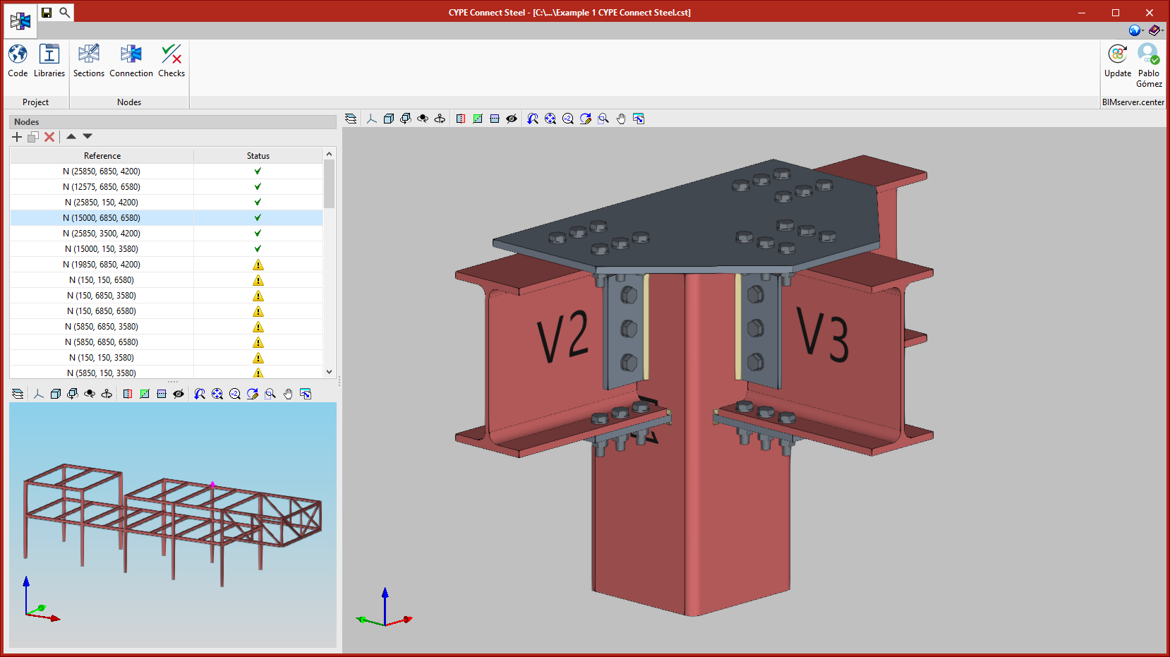
Workspace
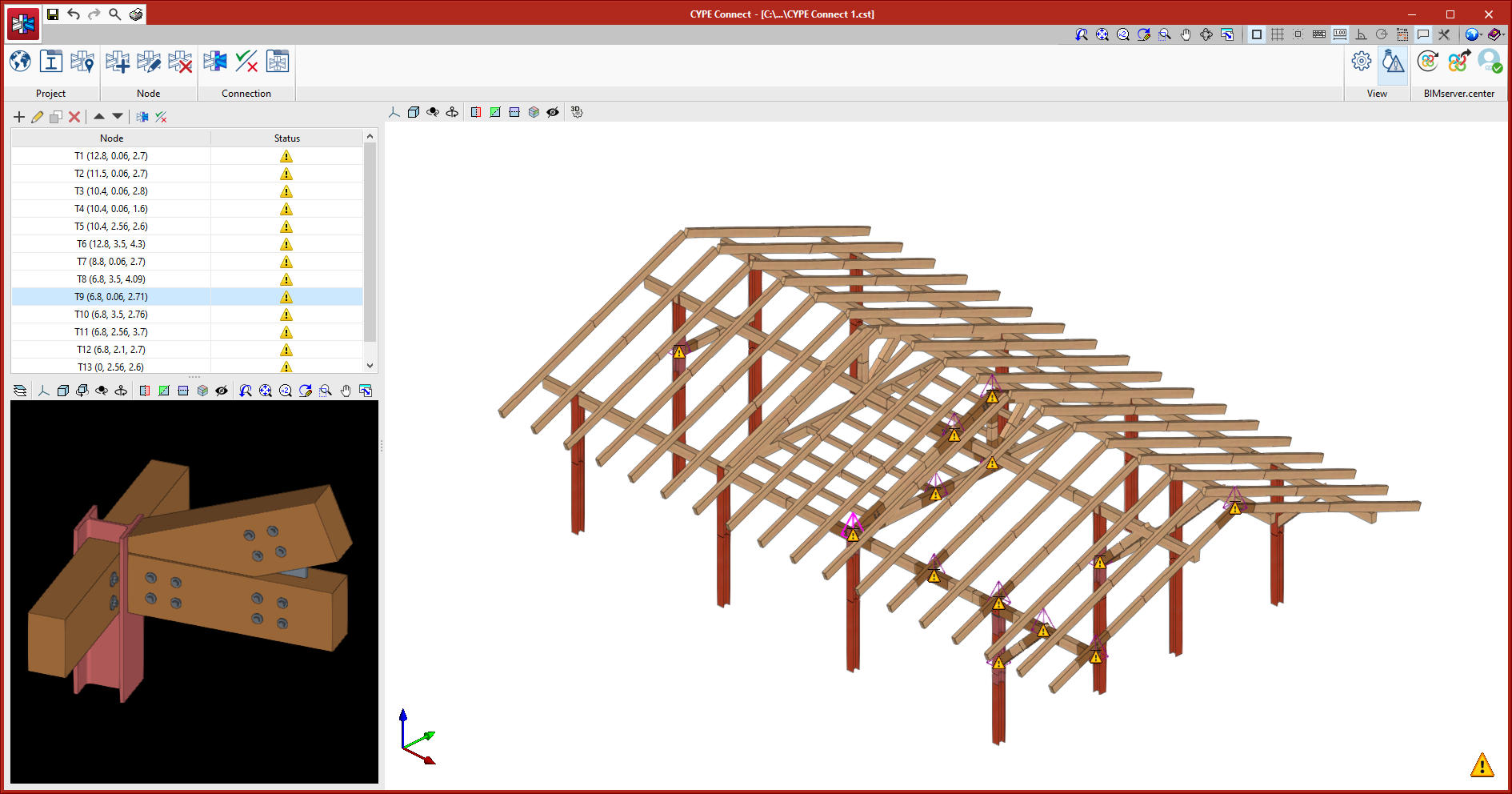
CYPE Connect has a "Top toolbar", a "Side menu" (with a list of nodes and a 3D view of the structure), and a "3D view of the connection" that corresponds to the node selected in the list of nodes.
Toolbar
The Toolbar, where the "Project" and "Nodes" sections are located, can be found at the top of the screen.
"Project" section in the Toolbar
This section contains two tools represented by the "Code" and "Libraries" buttons.
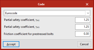
- Code
With this toolbar button, it is possible to select the design standard to be used. In the current version are available:
- Steel
- ABNT NBR 8800:2008
- AISC 360-16 (LRFD)
- "Código Estructural"
- EAE 2011
- Eurocode EN 1993
- IS 800:2007
- Timber
- Eurocode EN 1995
- Eurocode EN 1995
- Steel
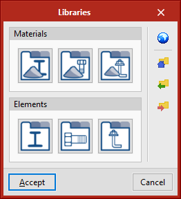
- Libraries
The "Libraries" button provides access to the various material and series libraries for sections, plates, bolts, and anchors. Materials, sections, and bolt series commonly used in Europe are included by default. The different libraries are presented in table mode, which allows easy copying and pasting of data from spreadsheets to customise the library to the users' liking. These libraries can be saved and shared with other users or workstations.
"Nodes" section in the Toolbar
This section contains the "Sections", "Connection" and "Checks" buttons.
- Sections
Allows users to edit the sections used in the node selected from the "List of nodes" side menu. - Connection
Allows users to access the modelling and analysis of connections. This tool opens the "Edit" panel, which is where the connection selected from the "Node List" in the side menu is modelled and analysed. The "Edit" panel also appears in the StruBIM Steel program. This panel, within StruBIM Steel, represents the integration of CYPE Connect into StruBIM Steel. - Checks
Displays node checks.
Side menu
A side menu is displayed on the left side of the CYPE Connect screen, made up of a "List of nodes" comprised in the project and a 3D view of the structure.
List of nodes
This list contains every node that makes up the project. Users can add, copy or delete nodes. As indicated above, users can edit the sections forming each node ("Sections" button in the toolbar), access the modelling and analysis of the connections ("Connection" button in the toolbar) or display node checks ("Checks" button on the toolbar).
3D view of the structure
The 3D view of the structure is displayed at the bottom part of the side menu.
Connection modelling and analysis
The "connection" button in the toolbar provides access to the panel for modelling and analysing connections. This panel can also be found in the StruBIM Steel program. Within StruBIM Steel, it represents the integration of CYPE Connect into StruBIM Steel.
The connection modelling and analysis panel has two tabs at the top: "Model" and "Analysis".
"Model" tab
From the "Model" tab, users can add the different elements that make up the connection and modify the sections of the node. It has a toolbar with the following options:
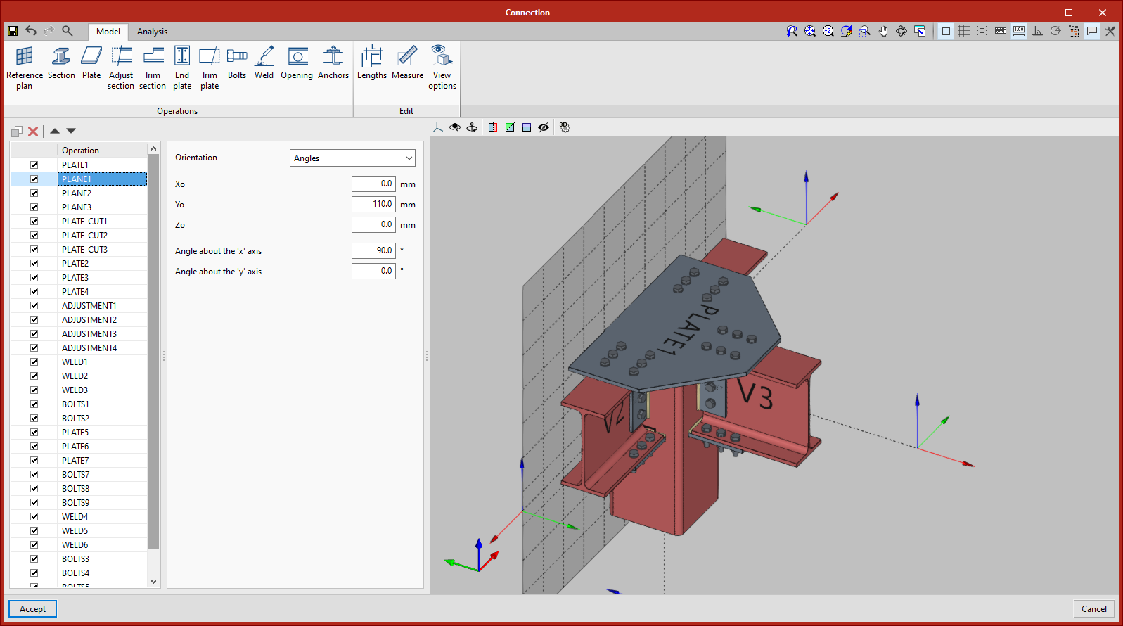
- Reference Plan
Reference plans are used to cut sections and plates, to make lengthening or shortening adjustments to these plans, or as a reference when adding plates.
- Section
This tool allows users to add additional sections to a connection in order to create an overhang, support elements, haunches, etc.
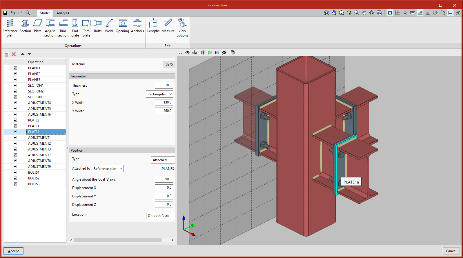
- Plate
With this tool users can generate plates that can be either rectangular or polygonal, in the latter type, they are defined based on coordinates (it is possible to copy and paste tables directly from spreadsheets).
- Adjust section
This tool allows users to lengthen or shorten a section, adjust it to another section, to a reference plan, or to a plate. - Trim section
Allows users to trim the selected section following the x and y magnitudes entered. Additionally, it allows them to define the type of trim: straight, with chord radius, or with drill. - End plate
This operation allows users to connect one section to another using an end plate. The welds from the section to the plate and the bolts between the plate and the section can be generated. - Trim plate
Allows a plate to be cut by another element. Users select the plate to be trimmed. The trim can be indicated according to the section's face, a previously defined reference plane or another plate.
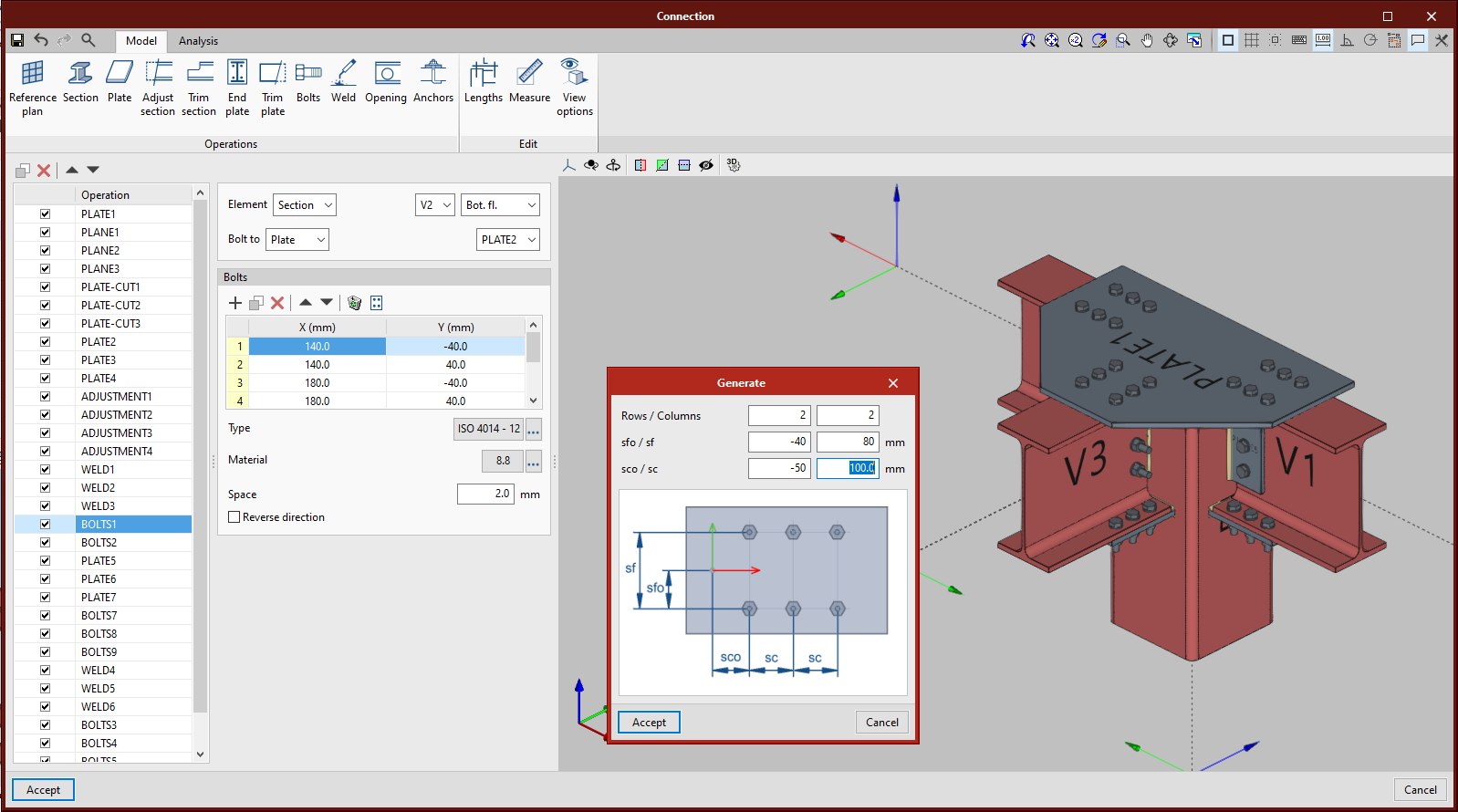
- Bolts
Used to define the bolted parts of the connection. The two elements being bolted together must be selected. If there are more than two, the connection's end elements must be indicated.
The bolts are defined by coordinates in relation to the reference system of the first selected element. Users can copy and paste directly from spreadsheets. The "Generate" tool (shown in the adjacent figure) can be used to create a bolt layout in rows and columns.
- Welds
Defines the welds between two elements. "Fillet" and "Lap" type weld connections are permitted. Both types are included in the analysis, but only fillet welds are tested. - Opening
Used to create openings in sections or plates. Openings can be circular or polygonal. - Anchors
This tool is used after defining the plate where the anchors should be placed. The placing system is similar to the one used to insert the bolts. - Lengths
With this option, users can edit the representation length and analysis of the sections. - Measure
This tool allows users to measure by selecting the connections’ elements. - Viewing options
These options show the opaque or transparent options, with or without reference axes, with or without labels, and give the choice of showing their total volume or not.
"Analysis" tab
After the connection has been defined, it is now possible to carry out the analysis and check, for which we have the following options in the "Analysis" tab:
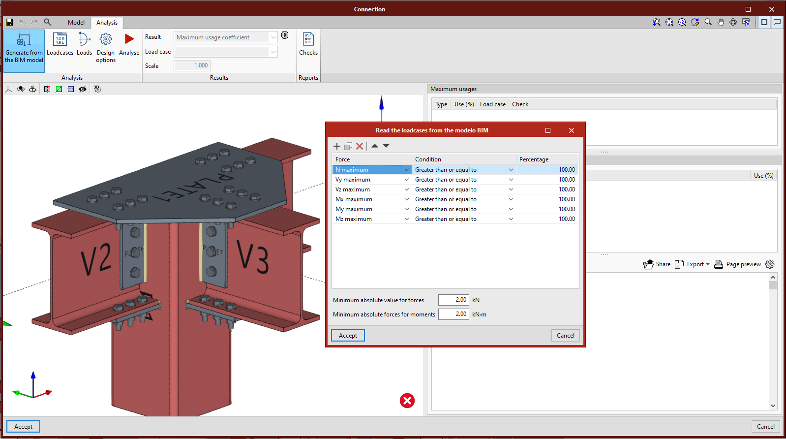
- Generation from a BIM model
This option will be available when the job has been created from a BIM model with forces. With this option, load cases will be generated and the loads of the sections involved in the connection.
This generation offers users the chance to filter the combinations of forces that will be examined. Not all combinations of forces have significant values, so it may be recommended to filter the number of combinations to be imported. By default, a filter is offered for each of the six forces. For each force, the combinations where a particular force exceeds a maximum value percentage will be examined, for both positive and negative signs. In addition to the force percentage filter, a minimum value can be set to examine the combinations or not.
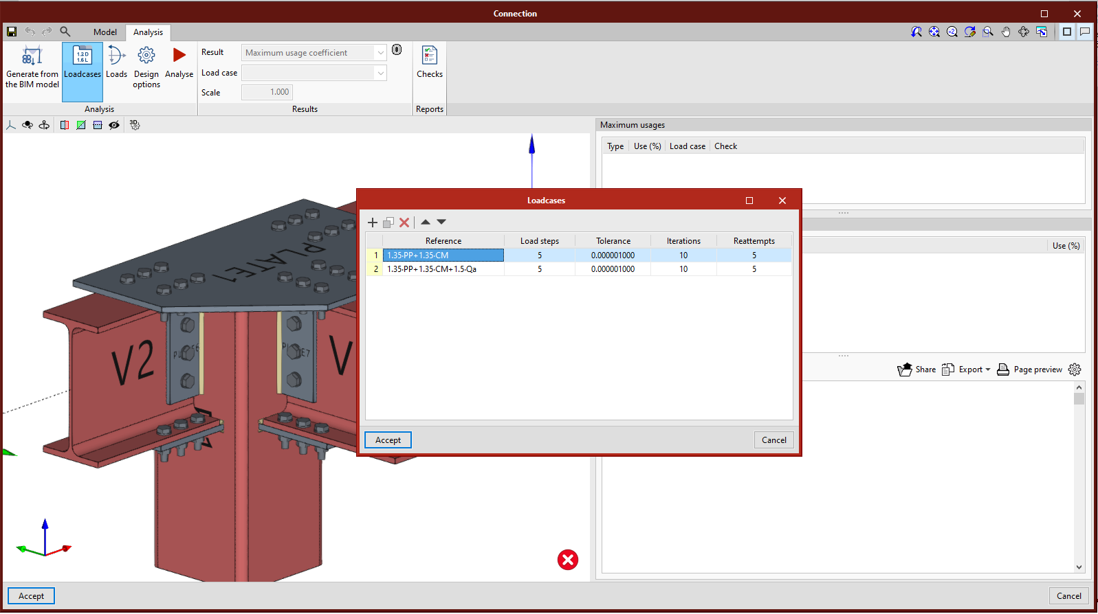
- Load cases
With this option, users can define the load cases they wish to consider in the connection analysis. These load cases can be generated from the BIM model or manually by users. For each load case the following parameters will be defined:
- Number of load steps
- Allowable tolerance to consider the convergence has been reached
- Maximum number of iterations in each load step
- Maximum number of attempts
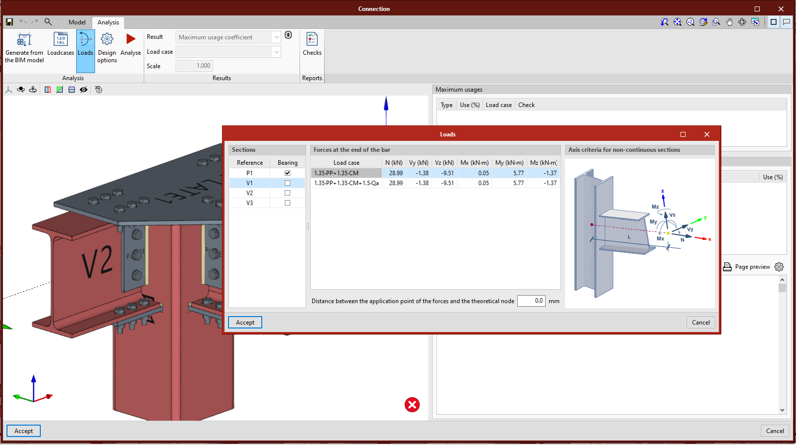
- Loads
This tool opens the "Loads" dialogue, where the acting loads for each section are defined for each load case (it is possible to copy and paste tables directly from spreadsheets). One of the sections must be the bearing section.
In addition to the loads, it is possible to define the application point of the forces for each section. This distance will also be taken from the BIM model, provided that the structure has been calculated considering the finite dimension of the nodes.
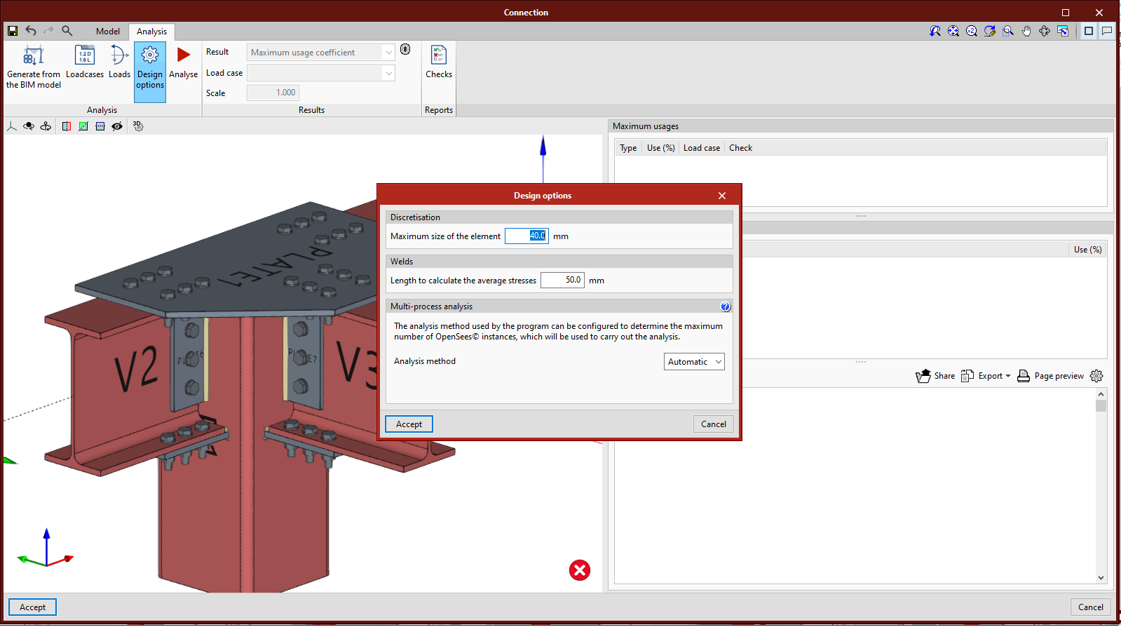
- Analysis options
In this section, the following can be defined:
- Maximum mesh size for the elements.
- The length for the analysis of the welds’ average bearing pressure.
- The multi-process analysis method of the OpenSees© calculation engine.
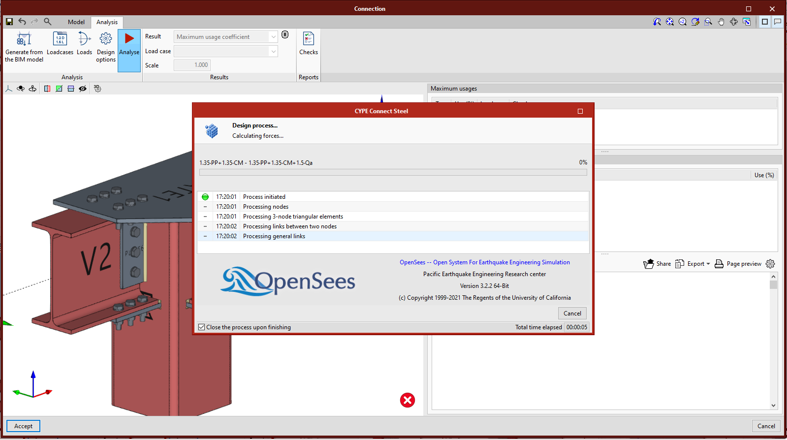
- Analysis
By clicking on the "Analysis" button, the force analysis and check will start. The first time we run the analysis, the implemented version of OpenSees© will be installed automatically.
- Results
In the "Results" section in the toolbar, users can check the following for each load case:
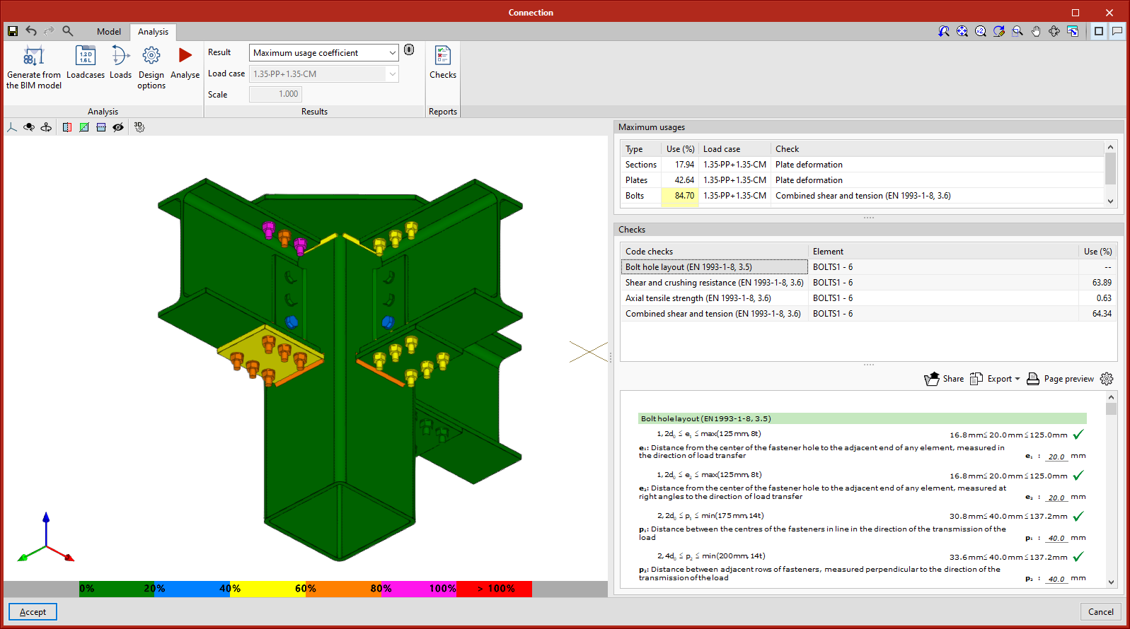
- Maximum usage coefficient
With this selection, elements are drawn in a colour that depends on their usage percentage. The colour scale is shown below the 3D view of the connection.
When clicking on a connection’s element, its checks are displayed on the right. When clicking on a free space in the 3D view, all checks are displayed.
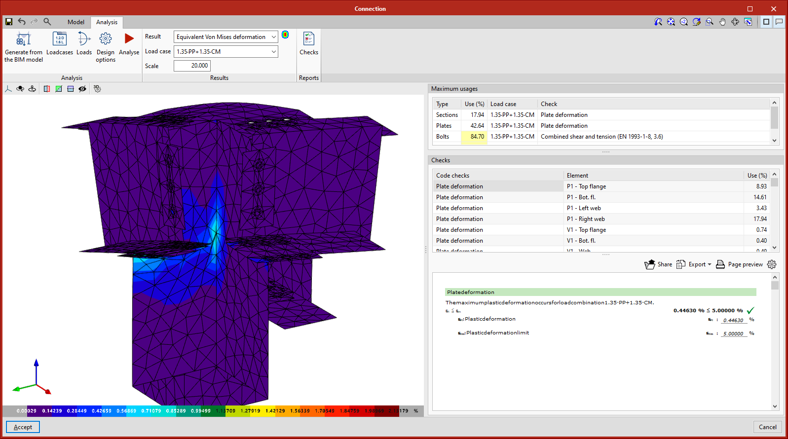
On the right, in the upper part of the checks, a table with the maximum usages depending on the element type is displayed. Deformation is checked for sections and plates, setting a plastic deformation limit of 5%.
For welds, the resistance of fillet welds is checked.
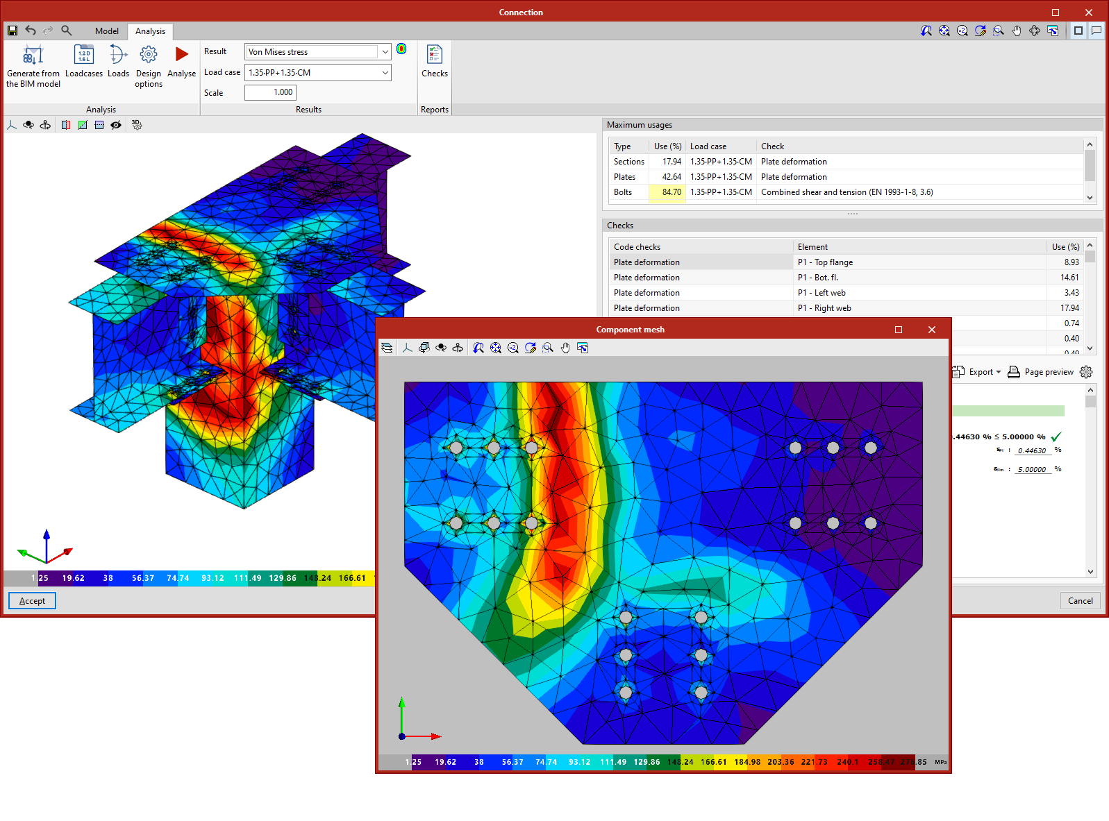
For bolts, the program checks the edge distance and the distance between bolts, the tensile resistance, shear and bearing resistance, and the interaction between shear and tension. In prestressed bolts, slip resistance is also checked. - Von Mises stress
With this option, elements are shown with their discretisation. By pressing on any shell, the results of that shell alone will be displayed in a dialogue. - Equivalent Von Mises deformation
With this option, the contour maps of "Equivalent Von Mises deformation" are represented. - Displacements
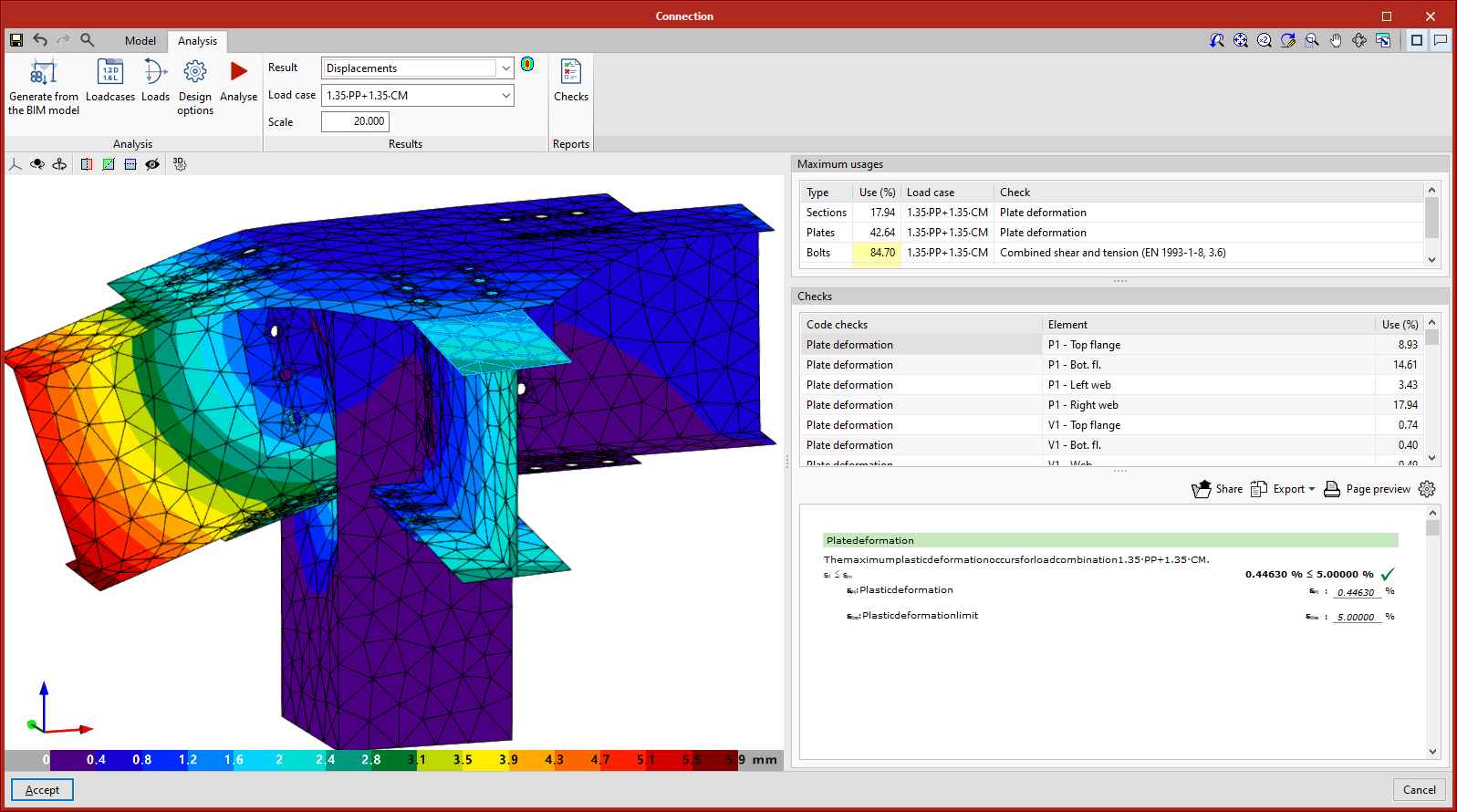
With this option, the displacement values are displayed on the connection’s analytical model view.
- Maximum usage coefficient
Structural timber element connections
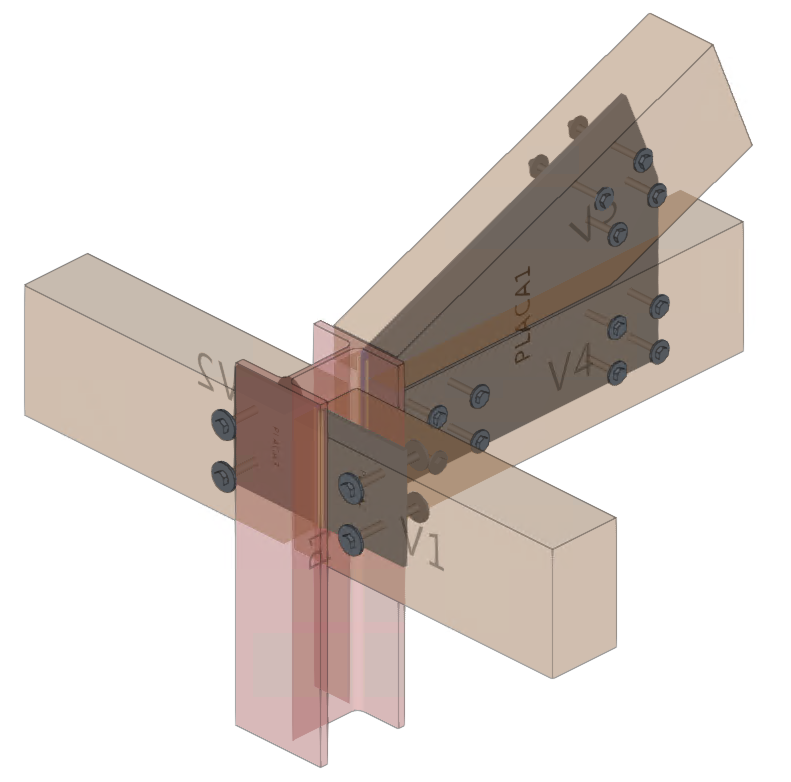
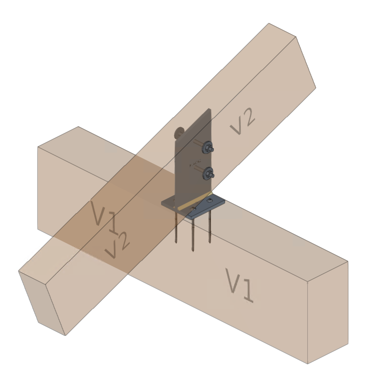
As of version 2022.d, CYPE Connect can model and analyse connections between structural timber elements as well as steel-to-timber elements.
The new CYPE Connect feature makes designing steel-to-timber connections easier. In these connections, forces are transmitted from one piece of timber to another by means of metal elements (fasteners and connections). The connection between the different structural timber elements is achieved by means of dowel-type fasteners and auxiliary steel elements such as metal sheets or sections. The timber elements transmit their forces via the fasteners (bolts, dowels and screws) to all the other elements they are connected to (steel sections and sheets).
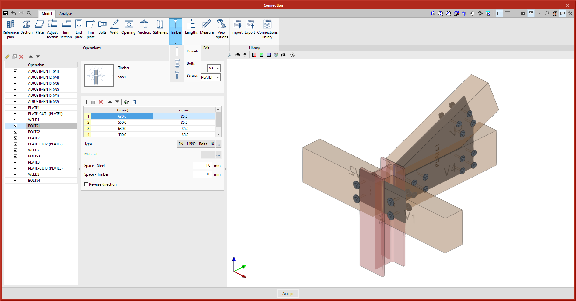
For modelling timber connections, the "Timber" operation has been implemented in the editing screen of a connection, which includes the tools "Bolts", "Dowels" and "Screws". In the rest of the operations available in the top bar of the program, the necessary modifications have been implemented for considering timber elements depending on the requirements of each operation.
After defining all the elements that make up the connection, the calculation can be carried out following the same procedure as for connections between steel sections.
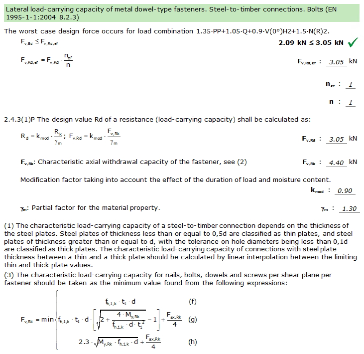
The program analyses the stresses and deformations of each of the connection components using Opensees© finite element software. With the acquired results, besides checking the steel elements in accordance with the selected steel code, the fasteners for timber are also checked according to the criteria in the chosen timber code.
For mechanical connections, dowel-type elements are an essential part of the load-bearing structure. By checking these fasteners in accordance with the requirements in the timber standard, we ensure that they are correctly designed to withstand and transmit the forces they will be subjected to. In version 2022.d, the criteria of Eurocode 5 (EN 1995-1-1) have been implemented.
More information
- Download, resources and available languages.
- License requirements
In order for CYPE Connect to be able to model and analyse connections between structural steel elements, the user license must have the corresponding permission.
In order for CYPE Connect to be able to model and analyse connections between structural timber elements, the user license must have the corresponding permission.
For steel-to-timber connections, the user license must have permissions for both connection types.
In any case, the OpenSees© calculation engine user license permission is required.
Tel. USA (+1) 202 569 8902 // UK (+44) 20 3608 1448 // Spain (+34) 965 922 550 - Fax (+34) 965 124 950